![]()
|
|
|
|
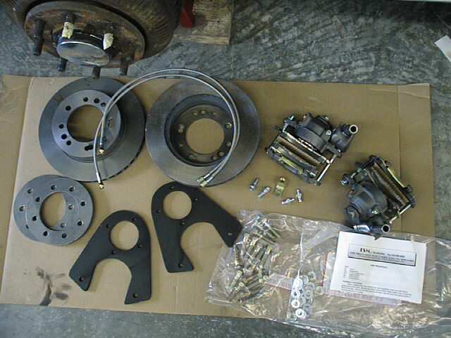
Click here for a May 19, 199 update. October '98 update: Brake Parts were obtained from TSM, The Streetrod Manufacturing Co. Inc. of Castle Rock, CO. Voice: 303-688-6882. Website: www.tsmmfg.com Stainless steel brakeline kit was obtained separately (and I'm brain-dead as to source at the moment).
Here is how it went.... I'm about to start my latest project... actually it's work -in-progress now: changing the rear brakes to discs and while in there to replace the 20+ year old brakelines with new stainless steel ones. I'm planning to pic-docu the proceedings and post the days activity each night courtesy of my Agfa digital camera. Click on any of the thumb-prints to view the picture. When viewing a picture please use the browsers back button to return to this page. Be sure to refresh the page in case your browser doesn't recognize Brake lines are from Classic Tube and the Disc Brakes are from TSM in Colorado.
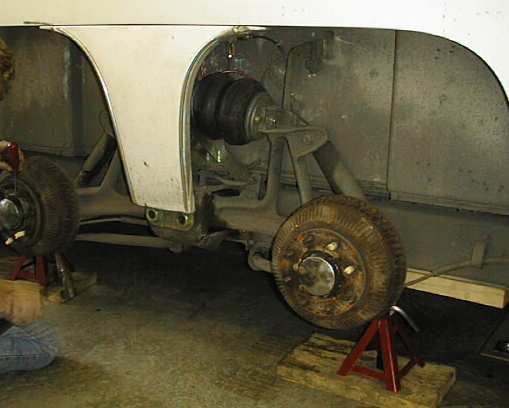
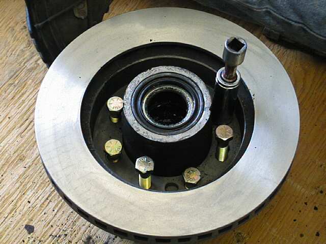
Day 1: Initial confusion, findings, solutions.
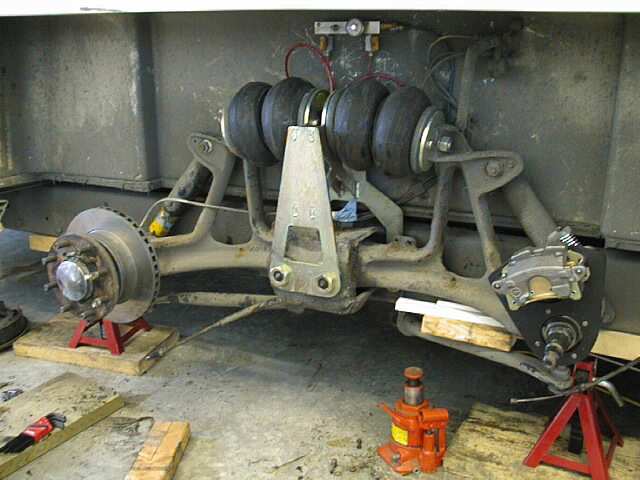
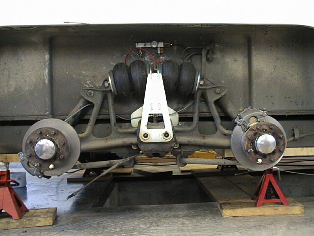
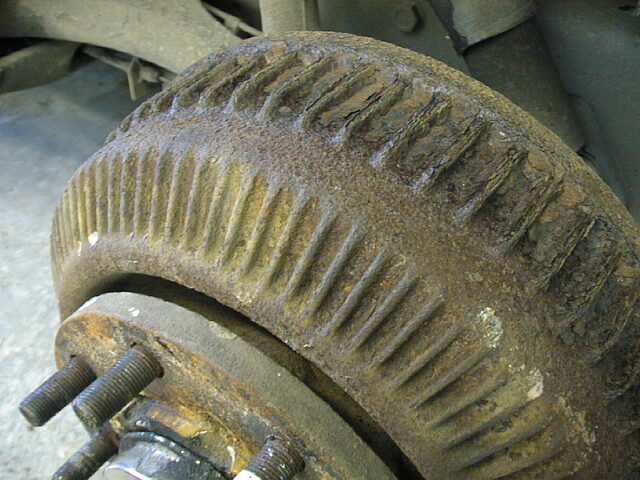
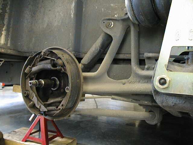
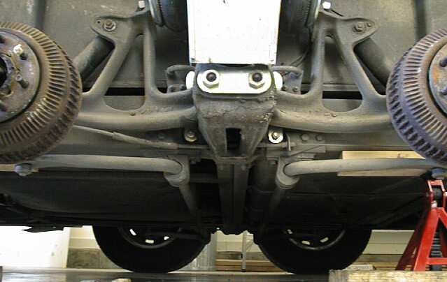
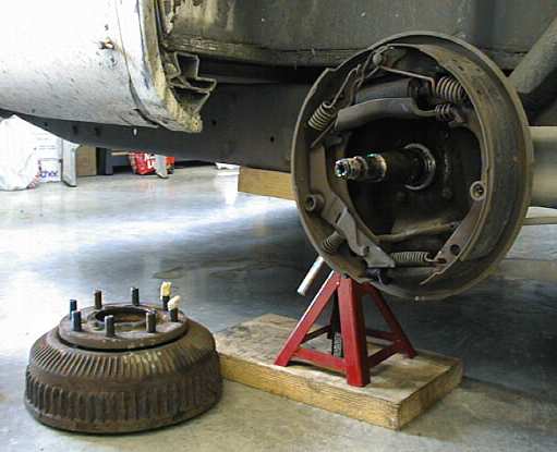
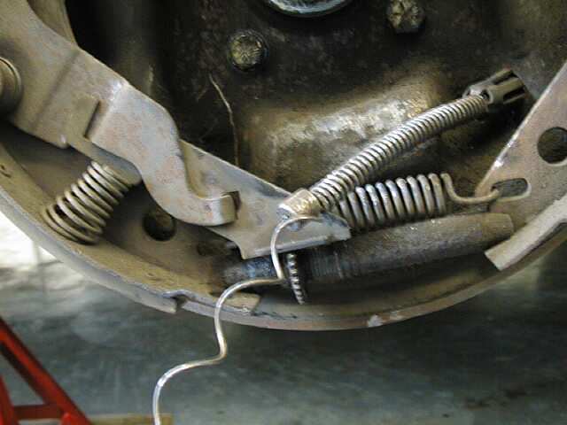
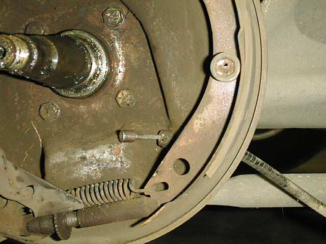
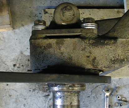
Last look at brakeshoes. In case you're wondering about the bar underneath the bogey,
that's the IDP Suspension torsion bar. A sideview of drums still in place and a better view if the IDP Suspension and of course, four bagger suspension system installed.
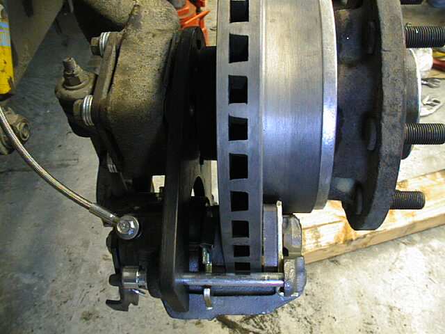
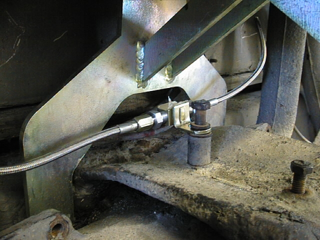
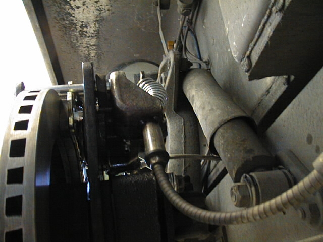
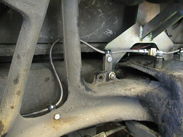
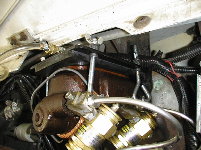
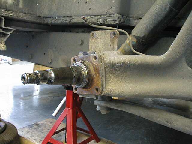
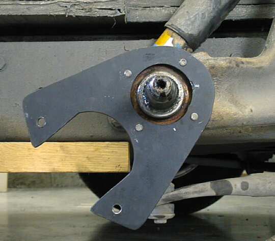
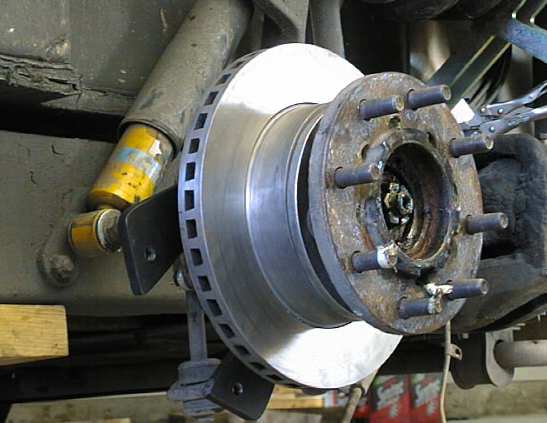
If you're planning to install this kit sometime in the future please take note of the rotation position of the back bracket. There'll be pictures. The position(s) used gave best fit for the emergency/parking brake cable. Note that rear rear and front rear brackets differ as to position. Lets get to work... First we pinch the brakehose.
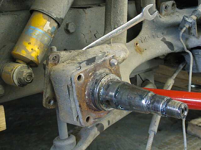
End of day one. Note the different rotational position of the front rear backing plate. This is the position required so as to connect the existing emergency/parking brake cable.
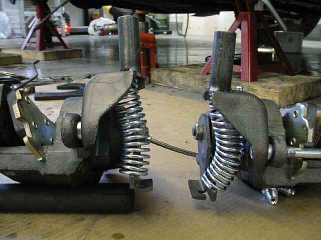
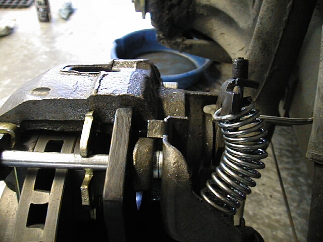
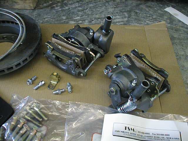
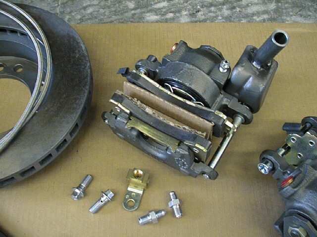
A close-up of the calipers' emergency/parking brake cable connection.
The existing spring on the cable is removed so as to not interfere with the new
spring/attachment scheme. The rear caliper was ground slightly at the parking brake
bracket. The second day was much more productive as much of what was learned on day one was put to use. Day 2: Front right and left side get completed.All the stuff learned on day 1 was put to (good) use. Right side was finished and left completed as well. Even got started on brakeline replacement.
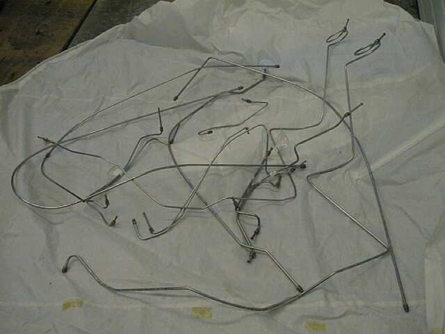
Day 3: The messy stuff.Completed brakeline replacement to the rear wheels. Bleeding was messy. Don't take shortcuts... follow directions from TSM, which are basically to remove the calipers while brakeline is connected and gravity bleed. After we did that it went much easier. Emergency/parking brake is another story. Had to lengthen the cable adjustment slightly. Front rear parking brakes get less force, due to cable run I assume. Rear adjusted nice and tight but I expect they'll only be slightly better than before. A real good solution would be to gain more cable travel when setting the hand brake. There is just not enough cable movement to apply the desired pressure. If anyone has ideas of how more cable pull could be achieved please email me. Some kind of ratchet handle would do the trick nicely. October '98 notation: I now have an electrically actuated parking brake. Pics will appear soon. Brakeline replacement to the rear brakes went reasonably smooth after realizing the single crossover in the rear was replaced with 2 pieces in the Classic Tubes stainless steel set. The areas that cross the frame rail will need some gentle adjusting to give a fit without tension. Plastic sleeving or rubber sleeving will be used to protect against brakeline to metal chafing... but that'll be day 4. Day 4: Tidying up and doing front brakelines.Front brakelines went smooth, just tedious. My GMC now has 550 degree Dot 3 in its new stainless steel veins. As part of cleaning up the aftermath I bent the old brakelines to fit them all into a box. Most of the lines bent smooth but 3 pieces snapped and/or kinked instead of bending. This is not to say the old line would not have given many more miles/years of service if left undisturbed but knowing that all is fresh will give me a little more peace of mind when smoking down the Grapevine (I5 to/from LA) next time. I will also be changing brakefluid every few years from now on after seeing the goop that came out and more importantly the pressure that was required to get the old stuff out compared to new/fresh/clean stuff.
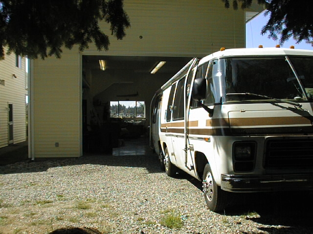
Day 5 will see the wheels go back on and the roll-out. While I don't plan
on doing any rearranging of dishes, etc. while running tests I do hope that I'll be able
to report by gut feel on whether it was all worth it Day 5: Out of the barn... briefly.The rig went back into the barn after a brief outing. Seems we have some stubborn air in the system. After many pints of brakefluid it's still in the barn. Time to research, reflect and re-plan another attack. Still optimistic it (the project) was a good thing to do, but..... The last chapter of brakes and brake lines.Finally success. Thanks to all GMC'netters that had advice and suggestions. We followed many suggestions and tried many variations. What finally worked is this: Capped off all four wheels at the tee. Checked brake pedal with and without engine running. There is approx. 1 inch more brakepedal travel with engine running. Right rear was done first as it's the furthest from the master cylinder. Uncapped and re-connected caliper to tee via braid line. Removed all clamps holding braid in place. Removed caliper from backplate and positioned it high with braid line flowing upwards and positioned so that bolt holes of caliper were straight vertical and bleed valve on top.
Right front rear, left rear rear and left front rear were each done in turn. After each wheel was completed and caliper re-installed the brakepedal travel was checked with engine off and running. Each wheel (caliper) absorbed about 3/16th to 1/4 inch of pedal travel. Then it was time to hit the road... End of story... almost.
Epilog:The jury is still out on whether the project was indeed effective and/or worthwhile. I think stopping distance has lessened, but it could simply be the desire to have it be less after all the trials and tribulations experienced during this project. Would I do it again or recommend it to anyone else? Probably, as it would now be a piece of cake all the way through. Is it a necessary enhancement? Perhaps. I'll let you know next time a for real panic stop elevates the pucker factor. That's really the only true gauge. What would I do different? There is no doubt that it would've been smoother had I done only brakelines first and discs later as a separate project. Clearer instructions from the vendor would've also helped but we all know there is no substitute to firsthand frontline suffering. One thing I would definitely do differently the next time is to establish and record the pre-enhance environment. In this case, what were the precise brakepedal positions before. I would also establish a stopping distance so that it could be used as a baseline reference after the enhance. As a recap I'd like to say that the actual conversion from drum to disc
was easy and went smooth. The project did not run into trouble until it came time to bleed
the system. Unfortunately for me I was the first to do all four rears. Perhaps a little
too much optimism expressed by the vendor, perhaps a little too much expectation and not
enough questions by the GMC'er (me). I only asked how many installations... didn't think
to ask how many with all four
The secret is out... if you're wondering who's doing all the work click here.
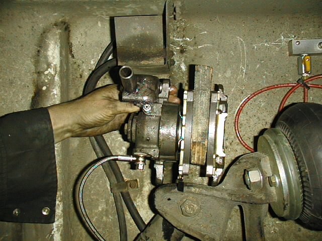
It's been a few miles now, actually it's been about 15,000 miles since the Disk Brakes were installed. The Jury is in... I definitely like them. Today was re-bleed the brakes day. Still remembering how tough it was last time around I looked for alternatives... and found an excellent Bleed Kit... more on that later. The reason I decided a re-bleed was in order was realy just for peace of mind. However, after getting started I noticed that the fluid on the front-brake chamber was highly discolored, actually red instead of clear. I don't know the cause but fluid was changed completely and I'll keep my eye on it. When the new brakelines and disk brakes were installed I used 550 degree DOT 3 fluid. This time I'm back to the standard 450 just in case it has a bearing on the discoloration. The pads on the right rear were worn out so got replaced. All others still have lots of wear left. Cause for the heavy wear on one wheel may be due to poor brake release or perhaps a parking brake that's ratcheting too close. Another item to keep tabs on. The disks ( rotors? ) on the streetside seemed slightly more dirst worn than the left side. No deep grooves, just a bit rougher than the left, which looks almost as good as when it was first installed. Bleeding the brakes with the new toy, the Speedy Bleed. The Speedy Bleed is a pressure bleeder. That means a constant pressure is applied via the master cylinder and all you need to do to bleed is to open the valve at each wheel. No hassling with trying to keep air from getting back in via the valve itself.
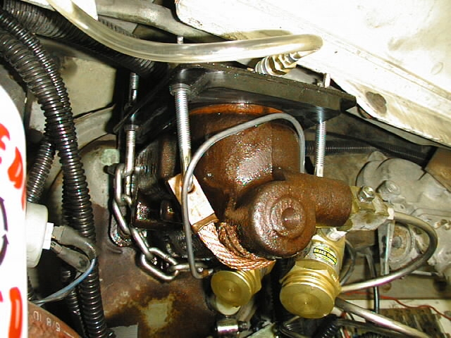
A plate is attached to the top of the master cylinder. The seal is via a thick rubber gasket and the plate is held tight by a chain and an improvised strap. We applied 20 lbs of air and regulated it down to about 15-17 with the regulator at the bottle. The bottle is filled with brake fluid and connected to air on the one side and the master cylinder on the other.
A view from the right. Note the chain in the rear and the improvised strap on the front to hold the lid on tight.
And a view from the left. To use this system with the front brakes the proportioning valve has to be held open. It was extremely easy to bleed with this gizmo and we did have air in two rear calipers. Brakes should work even better now. It would be relatively easy to build one of these. The critical pieces are the plate, gasket and hold-down. We started to, but when we found this one we put money on the table instead. Cost: C$289.00, much less in real dollars :-) Check out the Speed-Bleed Brake Pressure Bleeder Tool at the Speed Bleed website.
This page was last updated: Monday, April 26, 2004 05:53:50 PM |
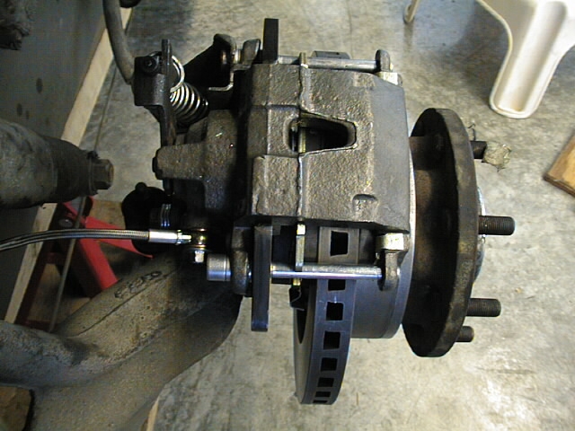
 Caliper
installed.
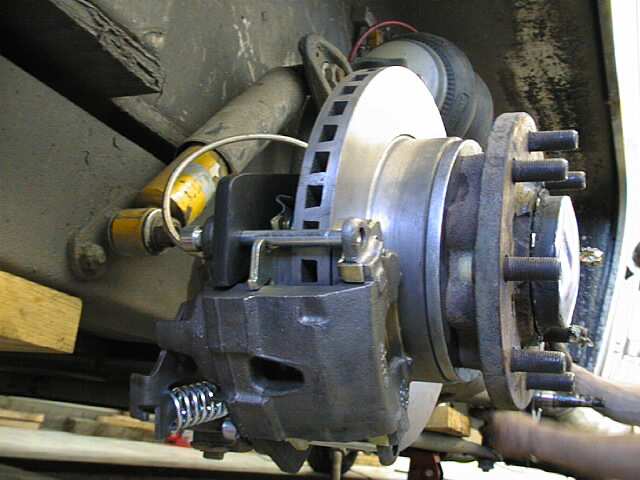
Caliper
installed.